The Personal Robot
Fall 2023 ECE 5725 Final Project
A Project By Syed Askari (sr2338) Raza and Shannya Niveyro(sn669).
Demonstration Video
Introduction
This project is identified as an autonomous robot that tracks the trajectory of a unique object and follows its path and ensuring that it maintains a safe distance from the object that its tracking. Moreover, along with object tracking, it avoids any obstacles in its path in order to prevent collision and ensure motion in the expected path. The robot movement is enabled using basic and inexpensive TT motors which are actually direct current gearbox motors. These motors are operated at varying duty cycles to achieve direction changes as per our requirements. The robot is connected to a camera that detects a unique red shape that the robot detects using Computer Vision techniques like masking, thresholding, and grayscale conversion. Using the camera feed, the robot follows the trajectory of the red object with varying speeds of the two wheels to steer in the required direction. Furthermore, in order to prevent collision with other objects we used ultrasonic sensors to detect the presence of any other objects in the robot’s way leading to a change in the direction of its motion to avoid any obstacles.

Project Objectives:
This project was pursued with the objective of building an autonomous robot by utilizing the capabilities of Raspberry Pi for interfacing and multi core processing. The project is a combination of electronics that are configured by multiple programming approaches enabled by the Raspberry Pi as the brain of the robot for decision making. The primary object of this project was to replicate the forklifts used in warehouses to identify objects and reposition them in storage using machine vision techniques like path and object tracking and detection.
Design
 The first goal achieved in this project was using OpenCV to access a camera feed and detect a red object. When detected, a bounding box would be formed around
the object of interest. The centroid of the target would be found and the difference bewteen the x and y coordinates of the centroid and the center of the camera frame would be calculated.
Based, on this difference, we wrote in for the car to either move left or right and forward or backwards until the centroid and frame center would be aligned. When aligned, nothing would be done.
The first goal achieved in this project was using OpenCV to access a camera feed and detect a red object. When detected, a bounding box would be formed around
the object of interest. The centroid of the target would be found and the difference bewteen the x and y coordinates of the centroid and the center of the camera frame would be calculated.
Based, on this difference, we wrote in for the car to either move left or right and forward or backwards until the centroid and frame center would be aligned. When aligned, nothing would be done.
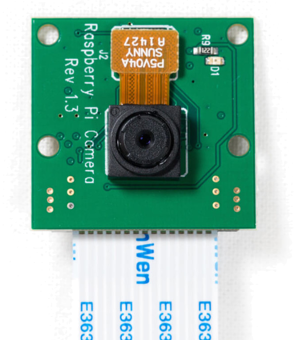 Next, the car was built using the assembly from Lab 2 in ECE5725, but with a PiCamera connected as well. The first issue encountered was the discoloration of the camera feed
whcih struggled to detect anything red. This was fixed by using filters on the camera inputs to rectify the coloration of the frames
so the correct colors would be registered in the feed.
Next, the car was built using the assembly from Lab 2 in ECE5725, but with a PiCamera connected as well. The first issue encountered was the discoloration of the camera feed
whcih struggled to detect anything red. This was fixed by using filters on the camera inputs to rectify the coloration of the frames
so the correct colors would be registered in the feed.
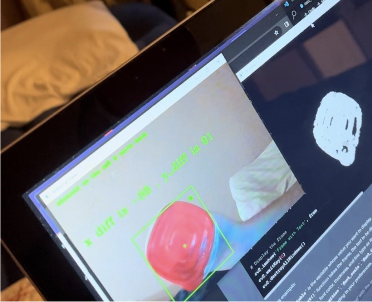 We applied Computer Vision techniques to allow detection of red coloured round objects and identify its center. This is the object that the robot should follow. To do this,
we converted the frame channels from RGB to HSV color channels. We then performed thresholding to allow detection of only objects
in the frame that had pixel intensities within a specific range to detect red objects only. A mask was created on the pixels in
the camera frame that lied between the given threshold range. Those objects were detected as the potential objects that the
robot should follow. The figure to the right shows the color masking on the sequential camera frames.
We applied Computer Vision techniques to allow detection of red coloured round objects and identify its center. This is the object that the robot should follow. To do this,
we converted the frame channels from RGB to HSV color channels. We then performed thresholding to allow detection of only objects
in the frame that had pixel intensities within a specific range to detect red objects only. A mask was created on the pixels in
the camera frame that lied between the given threshold range. Those objects were detected as the potential objects that the
robot should follow. The figure to the right shows the color masking on the sequential camera frames.
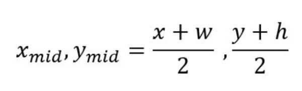 Since the object is supposed to follow just one particular red object, we extracted the total contours within the frame that were identified as red objects and extracted only the circular object that the robot is supposed to follow. The equation to the left calculates the center pixel coordinates of the object identified.
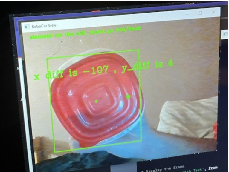 At this point, our robot is capable of detecting the one particular red object that it will follow. We now build a bounding box around the detected object and determine its center. The goal here for the robot is to track the center of the red object and try to align the center of the camera frame with the center of the object’s bounding box. We now simply build a bounding box around the center of the object.
We now have obtained a bounding box created with the center of the red object and have a fixed center of the frame. The camera frame resolution we use here is 320x240p primarily to fit the frame display on the PiTFT.
We now calculate the deviation in the x and y direction of the center of the object from the center of the frame. This metric actually determines the error that the robot has to minimize which is how it will track the movement of the red object. For this, we set two variables that calculate the difference in x and y direction between the two centers. The deviation between object and frame center is given by the equation below:

The total error error becomes the diagonal of the differences in x and y direction. Now that we have our camera object detection and tracking work, we move onto the hardware section which will actually move the robot in the desired manner.
The entire object detection and bounding box algorithm can be summarized as follows:
- Capture each frame using VideoCapture(0)
- Convert the RGB color channels to HSV channels using cvtColor
- Apply Thresholding to acquire objects with only red colours using inrange function
- Apply dilation and erosion to smoothen the boundaries of the objects to generate accurate bounding boxes using morphEx and morphDi
- Construct a bounding box around each object identified as red
- Select the object with circular contour so only one object should be detected at a time using findcontours function and find the biggest contour
- Compute the center pixel coordinates of the object’s bounding box
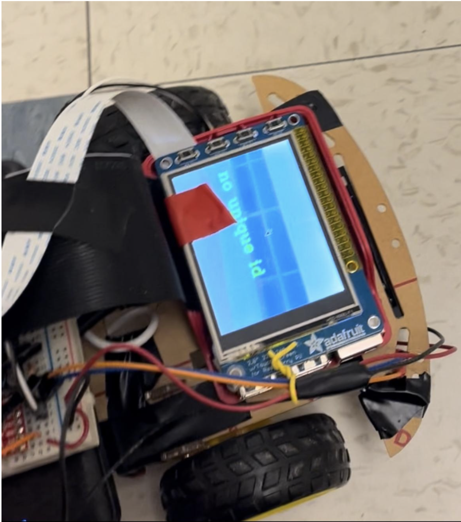
- Notify if no unique red object is identified
Hardware Design and Implementation
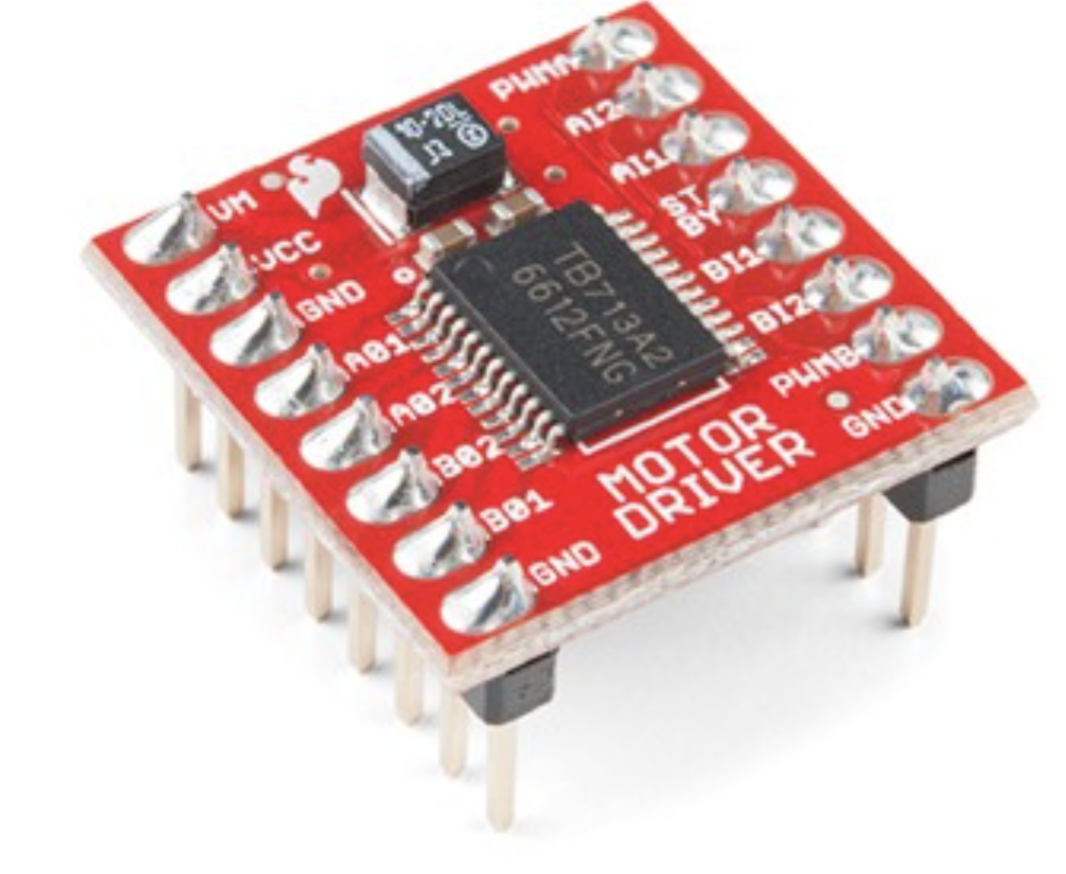
The movement of the robot is achieved with TT motors that are basic and inexpensive DC motors that are primarily used for cost effective robot projects. These motors operate with a 6V supply from a combination of AA batteries. The speed at which the motor rotates is determined by a PWM signal we generate at a given duty cycle at a frequency of 100Hz. The duty cycle we supply to the motor is determined by the amount the robot needs to move to track the object. We now connect the motors to ROB-14450 motor driver that takes in the PWM from GPIO output pins of the Raspberry Pi to rotate the motors at the desired speed. Below is the schematic of the motor driver.
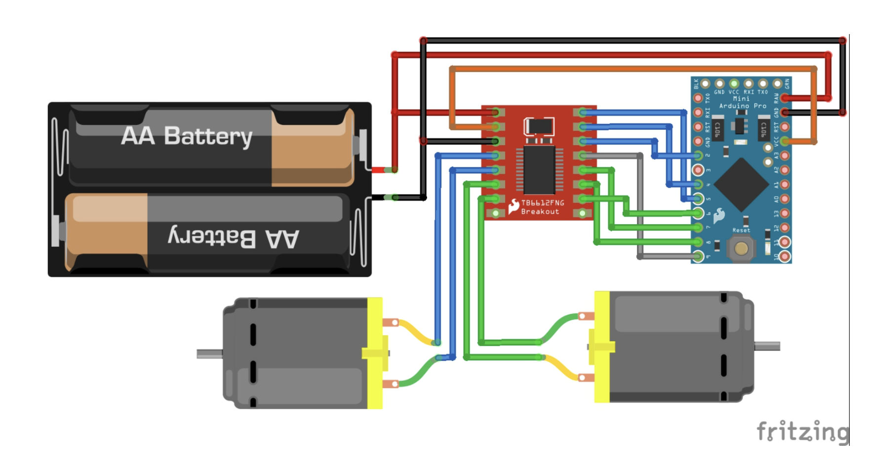
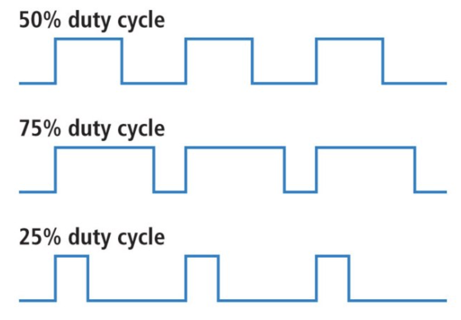
A total of 2 outputs from the GPIO pins are input to the Motor driver to determine the direction of rotation of each motor and another output as the PWM signal to the motor driver to rotate the motors. We set a base duty cycle of 50% which means this is the default speed of the motor when it needs to move in a straight direction without any steering required. The schematic below shows the connections made between the motor driver, motors, and the Raspberry Pi. Here’s a representation of a PWM signal at different duty cycles.
The GPIO Pins we use for PWM signals are 26 and 21. We now perform a basic test of the motor performance. There were a few challenges faced in terms of the motor rotation and movement of the robot. We powered up our Raspberry Pi with a power bank which didn’t provide the required voltage. As a result, the PWM signals were not supplied as per the required voltage settings. This caused the motors to rotate at a slower speed and therefore, we had to change the Powerbank and batteries for the main supply of the motors. Another problem we faced was the alignment of the wheels. Since the chassis we used was desired to be cost effective, there were a few issues with the assembly of the robot car that caused a bit of deviation in the movement of the robot due to variation in its alignment. However, we overcame this issue by adjusting the assembly and gluing the motors to the chassis to keep them firm. Moreover, the terrain on which the robot moved was also a key factor of its performance.
Now that we have our motors working and our initial software detection algorithm working, we combine the both to make the motor move in the direction of the object with respect to the center of the camera frame. Here are a bit of logics we inferred for more clarity in terms of the movement of the object.
If the red object is on the right of the robot it means the difference between the centers in the x directions is positive since the spatial axis in x direction is increasing from left to right. If the red object is on the left of the robot, it means the difference between the centers in the x directions is negative. Similarly, if the object is far from the robot, its difference from the camera frame in y direction will be negative since in the spatial axis the y axis increases from the top to bottom. Similarly if the object is too close, its difference from the camera frame will be positive. Now that we have built an understanding of the object’s position with respect to the robot’s position, we can move ahead and test out the motion of the robot.
PID Control and Pulse Width Modulation
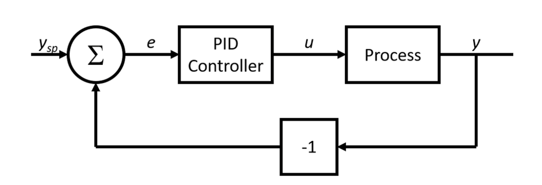
We now build up on another concept which is the rotation of motors to steer in certain directions. We know that if we need to move forward or backwards, we need to make sure that motors are moving in the same direction and at the same speeds. Any difference in speeds can lead to unwanted steering of the robot. This means both the motors are given the same duty cycle from the PWM signal. However, when we intend to move the robot to the left, we need to ensure that the right motor is moving at a higher speed compared to the left motor depending on how much we want to steer the robot in the left direction. The same intuition is followed when steering to the right. The primary goal now is to determine the right speeds for both the motors to move in either of the 4 directions to achieve center alignment with the red object’s center. This is achieved using Proportional-Integral-Derivative Controller which aims to minimize the error until it’s reduced to zero. The schematic below gives an overview of a PID controller.
The main intuition behind using proportional controller is that it takes the overall deviation in x and y direction (between the object’s center and camera frame’s center) as the error that it will minimize. The error is mapped as the duty cycle that is supplied to the motor. As the error keeps reducing, the duty cycle keeps reducing till the point where deviation in x and y directions is within the tolerance level where the error reduces to zero and the robot achieves its desired position with respect to the object’s center. Here, the output which is the new error (in x and y direction) is fed again to the input and the new duty cycle is generated based on the output that was fed as the input. This closed loop feedback control is performed till the error is within the desired tolerance level which is set to 30 in terms of the camera frame pixels.
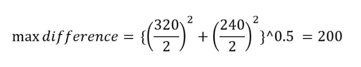
We initialized our coefficient for proportional controller as a fraction of the maximum duty cycle of 40% supplied to the motors depending on the error we have. The maximum error combined in both axes was 200 pixels that could be achieved given a resolution of 320x240p. For understanding, if the error or deviation between the two centers was 200, a maximum duty cycle of 40% added to the base duty cycle of 50% will be supplied to the motors to steer in a specific direction. This process required fine tuning of the proportional coefficient which was done annually by iterating between a range of values of the coefficient until the right value was achieved. This also took into account the terrain on which the robot was moving. However, after multiple iterations, we were able to achieve the desired motion of the robot. The equation below computes the maximum error possible.
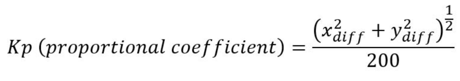
The following equation calculates the value of kp, the coefficient for proportional controller.
Ultrasonic Sensor Configuration
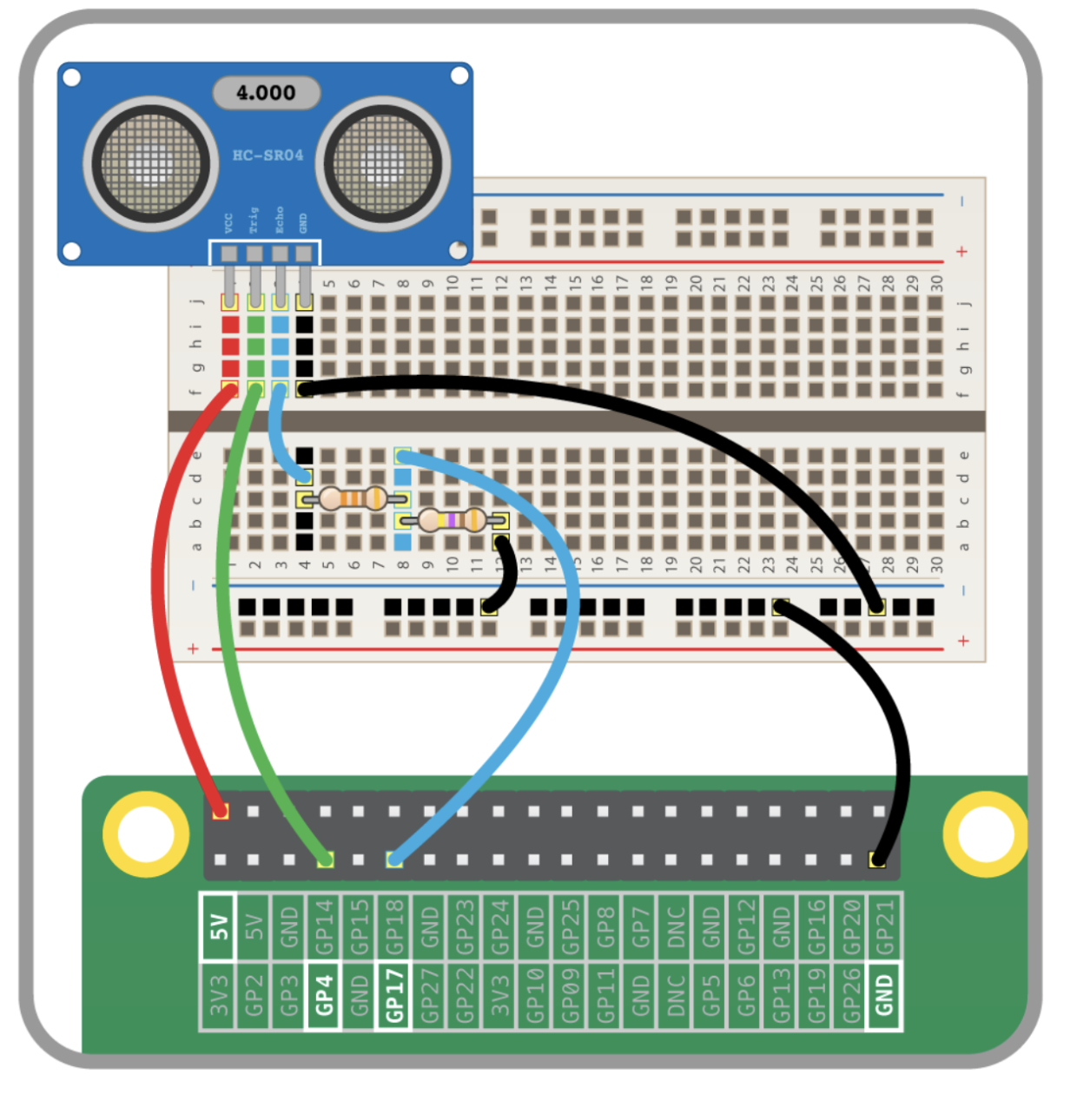
Finally, we intended to incorporate obstacle avoidance in order to prevent robot’s collision with any other undesired object in its path. For this, we simply use an ultrasonic sensor and by using the gpiozero package on Python, we initialize the reading of the sensor. We use the HC-SR04 ultrasonic sensor module to get the distance of the robot from an undesired object. The schematic below shows the circuit for the sensor. However, since we didn’t have the 470 Ohm and 330 Ohm resistors, we used 1k Ohm resistors as potential dividers. The sensor generated correct results.
The ultrasonic sensor basically reflects off an ultrasonic wave and returns it back to the receiver and the time it takes to receive the wave, we determine the distance based on the speed of sound which is 340m/s. The figure below gives an explanation of the fundamental concept behind operation of an ultrasonic sensor.
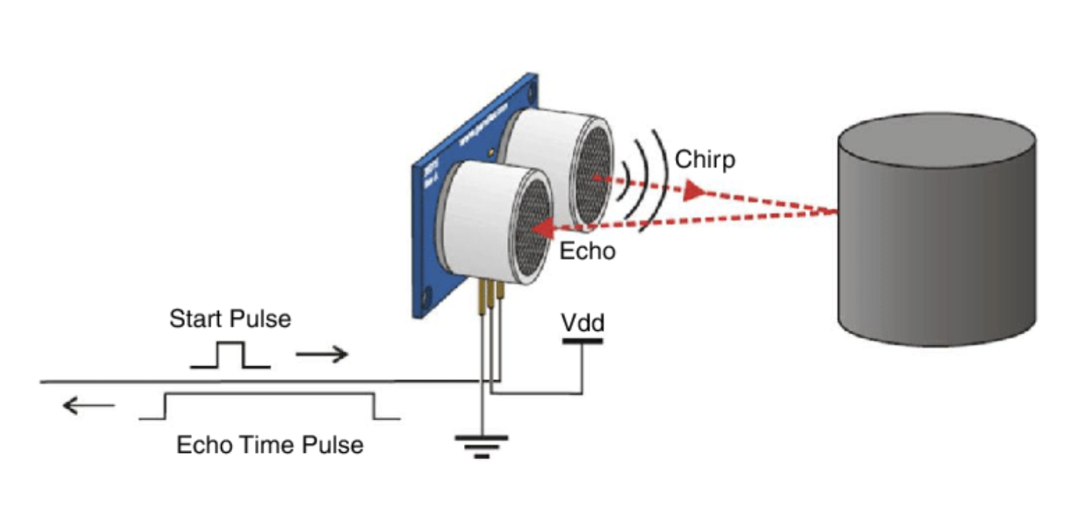
The equations below show how the sound speed is translated into distance from an obstacle.
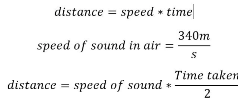
Note that we divide time taken by 2 because the time taken from transmitter to the receiver after bouncing off the object is twice the time taken to travel in from transmitter to object.
As per the program, whenever the robot detects an object at a distance of less than 5 centimeters, it reverses and changes its direction before continuing to track the object. However, this part has a catch. By default, the robot should follow this routine when it also detects the red tracking object within a distance of 5 centimeters. However, to resolve this, we added another condition. If the distance is less than 5 centimeters and the area of the bounding box around our object is less than its maximum area possible, only then the robot changes its direction. For understanding, this means that if the red unique object is very close to the robot and it is the object that the sensor detects, then the robot should not change its direction. Instead it should follow the trajectory and try to maintain the centers of the frame and object by moving back. After multiple tests, we successfully incorporated these logics to build an autonomous robot that tracks the red object and ensures that it does not strike into any other undesired objects in its way. To make the robot autonomous, we had to ensure that no external connections were established with it. To do this, we powered our raspberry pi with a 12V power bank and powered the motor driver with a 6V supply from a battery hooked to the robot assembly. One interesting challenge we faced was to generate the desired torque to move the robot on slippery terrains because the final assembly of the robot substantially increased its weight, which made it challenging to generate the required torque from these motors. For this, we changed our batteries and distributed the weight right above the wheels so they have a well established contact with the floor.
We displayed our real time camera feed on the PiTFT by using the Pygame package. Alongside, we added a start button that would start the object tracking of the object. Furthermore, using the physical buttons on the Raspberry Pi, we added the functionalities of quitting the object tracking routine and shutting down the Pi.
One more challenge that should be noted is the difference in lighting in the surrounding of the robot. Since the robot tracks red objects, if the lighting in the room was not well equipped, the shadows may manipulate the pixel intensities of the object we’re trying to track. Therefore, during testing, we made sure that the lighting is sufficient to detect the right colors of the objects.
To make the robot autonomous and independent of any connections, using the crontab in linux, we scheduled our program to start whenever the Raspberry Pi was rebooted. This meant that whenever we started our raspberry Pi, the program started with a start button showing. To quit the program we simply had to press button 17 on the PiTFT and to shutdown the Pi, we pressed button 22. Finally, after overcoming multiple challenges pertaining to change in physical surroundings and software bugs, we were able to test successful runs of the robot tracking the red object and avoiding any obstacles in its way.
Result
The process of testing at every step was filled with failures and required multiple iterations since the hardware, especially motors, are susceptible to changes in physical surroundings. However, fortunately, after multiple tunings and iterations in the software, hardware, and the assembly, we successfully implemented and demonstrated the operation of this robot as an autonomous machine that tracks the movement of the unique identifier object and avoids any obstacles in its way. We intended to add the functionality of object classification in the robot. However, since this version of Pi has a 4GB memory, it was not well equipped to perform Deep Learning for object classification. Therefore, it was not pursued due to processing limitations. Moreover, the robot we tried implementing the derivative controller as well to reduce oscillations while reducing the error. However, the motors are not as responsive, therefore, it did not improve the performance. One solution for the future would be to use brushless motors that are more synchronized and responsive to changes in duty cycle. Also, have a higher operating torque to respond to abrupt changes in the position of the object with respect to the camera’s center. Also, due to processing limitations and the constraint of displaying our camera feed on the PiTFT, we had to reduce the resolution of our camera feed to 320x240p. We can have better tracking with more responsiveness to changes in position of the object if were working with higher resolution which would allow the robot to track the object at a farther location. We can definitely implement it to allow even better tracking if we have more processing power and don’t have the constraint of displaying it on the PiTFT. However, to conclude, the robot achieved its goals with decent and notable results as depicted in our demonstrations.
Future Work
There’s a wide range of optimizations that can be made in this project to improve the functionality of the robot. By adding more processing capacity to the Raspberry Pi, we can implement object classification and while the root tracks the object, it will count the units of different type of objects that it sees on its way. This has a massive application in the industry where forklifts and robots are moved around the warehouses to count the units of different items resting on the shelves. This optimization is particularly focused towards the industry requirements. Moreover, we can stream the robot’s camera feed virtually to assess its performance without human intervention. Furthermore, we can use depth estimation to detect the distance to different objects to achieve better accuracy. However, that will require higher resolution cameras. This project already uses computer vision techniques put to use with image processing and electronics. We can surely add Deep Learning techniques for better object classification and make it into a robot that is a prototype for what is required in huge businesses. The possibilities for this robot are endless!
Conclusion
Overall, the project would be considered as a success. Since the start of this project, we invested a substantial amount of time in researching different techniques and compared their benefits in terms of processing speed and accuracy. Based on the research, we successfully performed numerous iterations at each step. Although there were failures along the journey, with thorough study of the underlying concepts, we were able to pinpoint the issues, and resolve them in the given time. This project can be classified as a n experience that amalgamated the learnings from course labs, discussions with the course staff, and resources shared by Professor Skovira. It was a significant learning experience particularly on how to identify bugs and resolve them. Whether it was the inaccurate object detection or the insufficient response of the motors, every failure was a learning experience for us and we absolutely cherish the completion of this project and hope that this project provides the motivation to future students to pursue more challenging and innovative projects with Embedded Systems.
Work Distribution
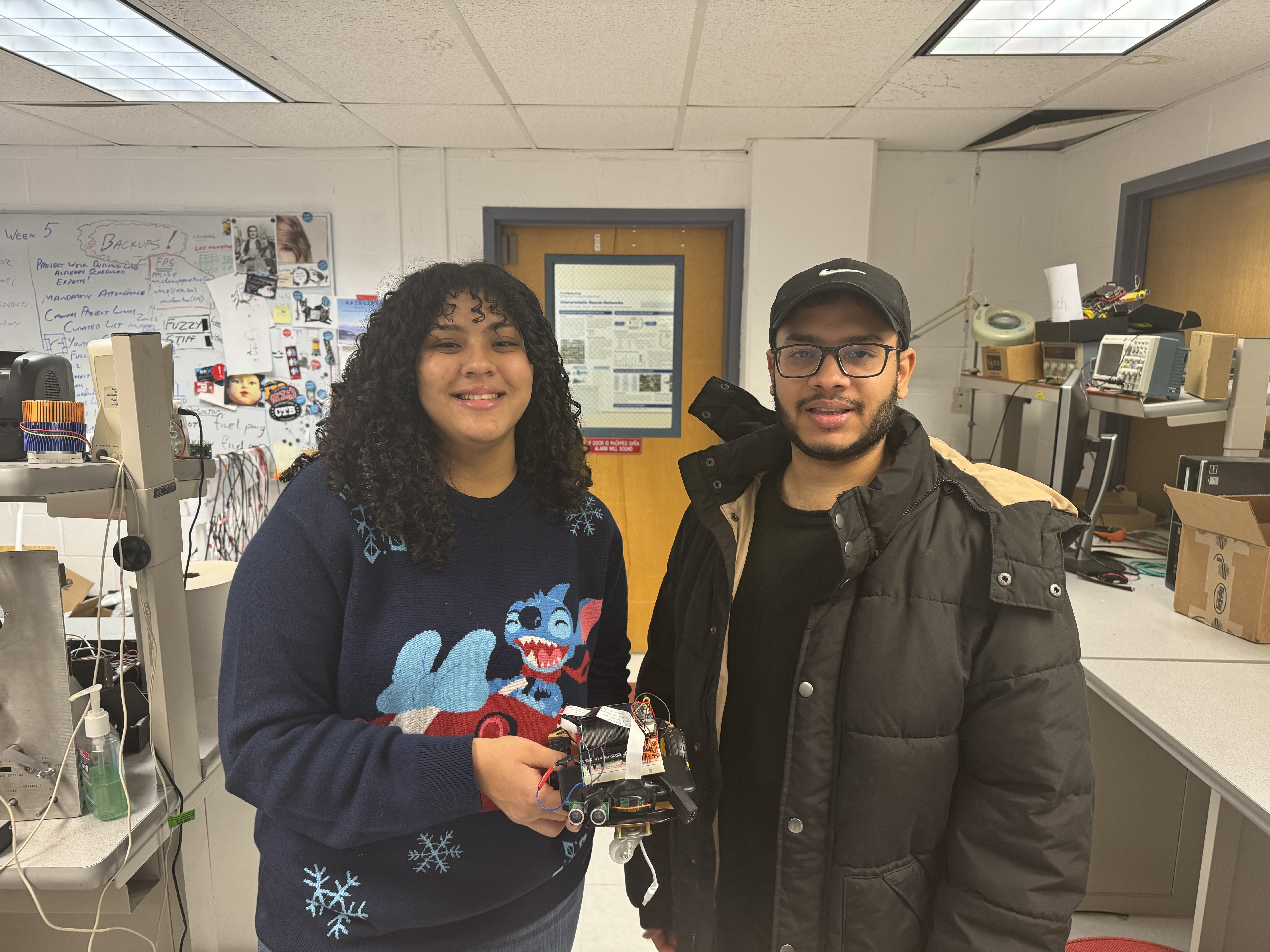
Project group picture

Shannya Niveyro
sn669@cornell.edu
Software integration

Syed Askari Raza
sr2338@cornell.edu
Hardware assembly and testing
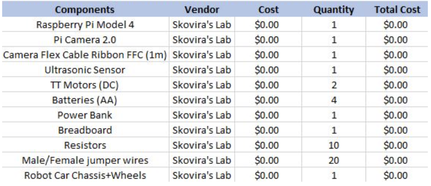
Bill of Materials
References
PiCamera DocumentTower Pro Servo Datasheet
Bootstrap
Pigpio Library
R-Pi GPIO Document
Pulse Width Modulation Documentation
Pulse Width Modulation
Color Tracking with PID
Using OpenCV with Live Camera Feed
Color-Based Object Detection with OpenCV and Python
OpenCV Video to Pygame
Code Appendix
#Importing all packages
#RPI.GPIO for using GPIO pins as inputs and outputs on the Pi
#cv2 used for Computer Vision tasks of the project
#numpy to use arrays to achieve computer vision tasks
#pygame to build a graphical user interface on the PiTFT and display camera feed on it
#os used to execute system commands like shutdown etc
#gpio zero is imported to make use of built in functions to use with ultrasonic sensor
import RPi.GPIO as GPIO
import cv2 as cv
import numpy as np
import matplotlib.pyplot as plt
import time
import pygame
from pygame.locals import *
#import cv2
#import numpy as np
import os
import sys
from gpiozero import DistanceSensor
from subprocess import call
#INITIALIZATIONS
#====================================================================================================
#declare variable that is an object with parameters regarding distance of the sensor
ultrasonic_front = DistanceSensor(echo=27, trigger=4)
#display the camera feed and pygame screen on the PiTFT
#framebuffer set to 0 since PiTFT is configured as 0 frame buffer when no external display is connected
os.putenv('SDL_VIDEODRIVER','fbcon')
os.putenv('SDL_FBDEV','/dev/fb0')
#initializing the variables for the object mid point as 0
x_mid =0
y_mid = 0
#initialization of kernels to perform dilation and closing
#This step smoothens the boundaries and contours of the red object
#this is an optional step. can be skipped for easier understanding and implementation
kernelOpen=np.ones((5,5))
kernelClose=np.ones((20,20))
#This thresh is basically the tolerence within which the object and frame centers would be considered aligned
thresh = 30
#the frequency of PWM signal generated and supplied to the motor driver
freq = 100
#This is the base duty cycle given to the motors set at 50%.
#it is changed to float because it works to mitigate the error so it can be computed in decimals as well
baseSpeed = float(50)
#this is the maximum duty cycle that will be added or subtracted from the base duty cycle based on the error generated
pwmBound = float(40)
#this is the maximum error that can occur in terms of pixel differences
cameraBound = float(200)
#we find the coefficient for proprotional controller. This decides how much of the 40% duty cycle to add or subtract from the base sppeed
kp = pwmBound/cameraBound
#initialize the error to 0
error = 0
#GPIO INITIALIZATION
#=============================================================================
#PWM AND MOTORS INITIALIZATION
#Pins initialization
GPIO.setmode(GPIO.BCM)
GPIO.setup(17, GPIO.IN, pull_up_down=GPIO.PUD_UP) #pull up
GPIO.setup(22, GPIO.IN, pull_up_down=GPIO.PUD_UP) #pull up
GPIO.setup(23, GPIO.IN, pull_up_down=GPIO.PUD_UP) #pull up
GPIO.setup(27, GPIO.IN, pull_up_down=GPIO.PUD_UP) #pull up
GPIO.setup(13, GPIO.IN, pull_up_down=GPIO.PUD_UP) #pull up
GPIO.setup(4, GPIO.IN, pull_up_down=GPIO.PUD_UP) #pull up
GPIO.setup(5, GPIO.OUT)
GPIO.setup(6, GPIO.OUT)
GPIO.setup(26, GPIO.OUT)
GPIO.setup(21, GPIO.OUT)
GPIO.setup(16, GPIO.OUT)
GPIO.setup(20, GPIO.OUT)
#DISABLE MOVEMENTS AT THE START
GPIO.output(5, False)
GPIO.output(6, False)
GPIO.output(26, False)
GPIO.output(21, False)
GPIO.output(16, False)
GPIO.output(20, False)
#===============================================================================
#CALLBACK FUNCTION DEFINE
#===============================================================================
# Pin 26 is set to give PWM signal to the right side motor whereas pin 21 will give a PWM signal to the let side motor. They are fed to the motor driver
right_pwm26 = GPIO.PWM(26, freq)
left_pwm21 = GPIO.PWM(21, freq)
#start the motors at a 0 duty cycle initially
right_pwm26.start(0)
left_pwm21.start(0)
#frequency and duty cycle initialized for motor operation
#This function is executed when button 17 is pressed. It quits the program when button 17 is pressed
def GPIO17_callback(channel):
global robot_loop
robot_loop = False
left_pwm21.ChangeDutyCycle(0)
right_pwm26.ChangeDutyCycle(0)
print('should quit')
print ("Button 17 pressed.")
#command to initialize the execution of GPIO17_callback function when button 17 is pressed
GPIO.add_event_detect(17, GPIO.FALLING, callback = GPIO17_callback, bouncetime = 300)
#We also need the functionality of shutting down the Pi and the program by a button press. When button 22 is pressed it shuts down the program and the Pi
def GPIO22_callback(channel):
#global robot_loop
robot_loop = False
left_pwm21.ChangeDutyCycle(0)
right_pwm26.ChangeDutyCycle(0)
call("sudo shutdown -h now", shell=True)
print('should shutdown')
print ("Button 22 pressed.")
#command to initialize the execution of GPIO22_callback when button 22 is pressed
GPIO.add_event_detect(17, GPIO.FALLING, callback = GPIO17_callback, bouncetime = 300)
#=============================================================================================
#DEFINING FUNCTIONS TO MOVE THE ROBOT IN GIVEN DIRECTIONS
#==============================================================================================
#Defining functions to move the motors in response to PID
#FUNCTION TO MAKE THE ROBOT MOVE FORWARD. THE GPIO PINS ARE SET TO HIGH AND LOW ACCORDINGLY TO ACHIVE FORWARD MOTION
def forward(rightPwm, leftPwm):
right_pwm26.ChangeDutyCycle(rightPwm)
GPIO.output(6, GPIO.HIGH)
GPIO.output(5, GPIO.LOW)
left_pwm21.ChangeDutyCycle(leftPwm)
GPIO.output(20, GPIO.HIGH)
GPIO.output(16, GPIO.LOW)
#FUNCTION TO MAKE THE ROBOT MOVE BACKWARD. THE GPIO PINS ARE SET TO HIGH AND LOW ACCORDINGLY TO ACHIVE BACKWARD MOTION
def backward(rightPwm, leftPwm):
right_pwm26.ChangeDutyCycle(rightPwm)
GPIO.output(6, GPIO.LOW)
GPIO.output(5, GPIO.HIGH)
left_pwm21.ChangeDutyCycle(leftPwm)
GPIO.output(20, GPIO.LOW)
GPIO.output(16, GPIO.HIGH)
#THIS FUNCTIONS SETS THE ROBOT TO REST. CHANGES THE DUTY CYCLE TO 0
def pwmStop():
right_pwm26.ChangeDutyCycle(0)
left_pwm21.ChangeDutyCycle(0)
#===========================================================================================
#INITIALIZING THE FRAME RESOLUTION OF THE PI CAMERA
new_width = 320 #640 # Replace with your desired width
new_height = 240 #480
#capturing the frame from Pi camera which is established as camera 0 or the default camera
cap = cv.VideoCapture(0, cv.CAP_V4L) #0 stands for webcam 0
#condition to exit the program if no camera is detected
if not cap:
print("!!! Failed VideoCapture: unable to open device 0")
sys.exit(1)
#============================================================================================
#PYGAME BUTTON AND DISPLAY INITIALIZATION
#============================================================================================
#pygame initialization
pygame.init()
#display set at the same size as the camera frame
screen = pygame.display.set_mode([320,240])
# Colors
white = (255, 255, 255)
black = (0, 0, 0)
green = (0, 255, 0)
red = (255, 0, 0)
#font and button size of the start button
font = pygame.font.Font(None, 18)
button_radius = 35
button1_x, button2_x, button3_x = new_width // 2, new_width // 2, new_width // 2
button_y = new_height // 2
#robot_loop runs after the start button is pressed. hence it is currently false
robot_loop = False
# Main loop - This loops detects if Start button is pressed. Until then the robot does nothing. When the start button is pressed, the program goes out of this loop and into the robot_loop
first_button = True
#==============================================================================================
#Start of the loop which detects if the start button is pressed
#the robot program edoes not start until the start button is pressed and this while loop ends
while first_button:
#This loop only checks in every run if the start button is pressed. If the button is pressed the first button will set False to get out of this loop and the next loop which is the robot program loop will start
for event in pygame.event.get():
if event.type == pygame.QUIT:
running = False
if event.type == pygame.MOUSEBUTTONDOWN:
if event.button == 1:
x, y = event.pos
start_dist1 = ((x - button1_x) ** 2 + (y - button_y) ** 2) ** 0.5
#this condition cheks if the press is at a distance within the button radius
if start_dist1 <= button_radius:
#if the start button is pressed, the robot loop is set to start whereas this loop will end
robot_loop = True
first_button = False
#These are generic process codes to execute pygame screen display
screen.fill(white)
#Draw the start button circle of the initlaized raidus and green in colour
pygame.draw.circle(screen, green, (button1_x, button_y), button_radius)
#the text the button should have and finally blit the text rect object with the text iteself
text1 = font.render("Start", True, white)
text1_rect = text1.get_rect(center=(button1_x, button_y))
screen.blit(text1, text1_rect)
#show the display
pygame.display.flip()
#=========================================================================================================
#Here the robot loop actually starts.
#=============================================================================================================
i=0
while robot_loop:
#frame variable stored the arrays of pixel intesities from the video capture
misc, frame = cap.read()
#this is just a counter of the frames recorded
i += 1
print(i)
#we resize the frame to 230x240p and rotate it by 180 degrees since the camera was installed upside down due to assembly limitations
frame = cv.resize(frame, (new_width, new_height))
frame = cv.rotate(frame, cv.ROTATE_180)
#CONVERT FRAME FROM BGR TO HSV
hsv_frame = cv.cvtColor(frame, cv.COLOR_BGR2HSV)
#red color
#these are the highest and possible RGB values for different shades of red
low_red = np.array([161,155,84])
high_red = np.array([179,255,255])
#create a mask for pixels that have their values within the given ranges
red_mask = cv.inRange(hsv_frame, low_red, high_red)
#performing morpohlogical filtering on the red objects to smoothen the boundaries
maskOpen=cv.morphologyEx(red_mask,cv.MORPH_OPEN,kernelOpen) #this is opening
maskClose=cv.morphologyEx(maskOpen,cv.MORPH_CLOSE,kernelClose) #we close the contours here
contours, hierarchy = cv.findContours(red_mask, cv.RETR_TREE, cv.CHAIN_APPROX_SIMPLE)
#we sort the contours in order of area. The biggest contour which will be our red object wil only be detected further
contours = sorted(contours, key=lambda x:cv.contourArea(x), reverse=True)
#Now we create a bounding box around the contour and the coordinates of the box are x, y, x+w, y+h
for cnt in contours:
(x,y,w,h) = cv.boundingRect(cnt)
#creates a rectangle
cv.rectangle(frame,(x,y) , (x+w, y+h) , (0,255,0), 2)
#THIS IS IMPORTANT!
#THIS COMPUTES THE CENTER COORDINATE OF THE BOUNDING BOX OF THE UNIQUE RED OBJECT
x_mid = int((x + x+ w)/2)
y_mid = int((y+y+h)/2)
break
#HERE WE COMPUTE THE DEVIATION BETWEEN OBJECT CENTER AND FRAME CENTER BOTH IN X AND Y DIFFERENCE
x_diff = x_mid - frame.shape[1]//2
y_diff = y_mid - frame.shape[0]//2
#store the distane from the nearest object from the ultrasonic sensor
distance = ultrasonic_front.distance
#This condition says that if there are no contours which means no red object detected then do the following
if len(contours) == 0:
#print on the screen that no unqiue object is detected
cv.putText(frame, str('no unique id') , (20,150) , cv.FONT_HERSHEY_COMPLEX, 1.0, (0,255,0), thickness=2)
#set the duty cycles of both motors to 0 which means to stop the robot movement
pwmStop()
#If there is a contour, then do the following
else:
#print x_diff and y_diff on the screen
cv.putText(frame, str(f'x diff is {x_diff} , y_diff is {y_diff}') , (20,150) , cv.FONT_HERSHEY_COMPLEX, 1.0, (0,255,0), thickness=2)
cv.circle(frame, (x_mid,y_mid) , 4, (0,255,0) , thickness=-1) #thickness =-1 if you want to fill the circle
cv.circle(frame, (frame.shape[1]//2,frame.shape[0]//2) , 7, (0,255,0) , thickness = -1)
#Implementation of PID!!!
#We compute error by combining the error in x and y directions and taking the diagonal/hyptoneuse
error = result = (x_diff**2 + y_diff**2)**0.5
#output the desired duty cycle by multiplying kp with the error.
#this basically tells how much
pwmOut = abs(kp*error)
area = (x+w)*(y+h)
#This condition checks that if the sensor detects an object within 5 cm to it but that object is not the red object which means its an obstacle then it will back up and change it direction to avoid obstacle avoidance
if distance < 0.05 and area < 76800:
backward(70,70)
time.sleep(0.7)
forward(30,70)
time.sleep(0.7)
forward(70,30)
time.sleep(0.3)
forward(70,70)
time.sleep(0.7)
pwmStop()
#For other conditions, do this routine
else:
#Conditions for the cases where x_diff is greater than the tolerence of 30. x_diff>thresh means the object is on the right of the robot
if x_diff > thresh:
#if y_diff is greater than thresh it means the red object is too close so the robot moves backward and towards left so it aligns with object in both x and y directions
if y_diff > thresh:
cv.putText(frame, str('element on the right & move back pls') , (20,20) , cv.FONT_HERSHEY_COMPLEX, 0.5, (0,255,0), thickness=2)
#MOVE backward AND RIGHT
backward((baseSpeed+pwmOut) , (baseSpeed-pwmOut))
#if y_diff < thresh this means the object is far from the robot so the robot moves forward and to the right to align with the object that was on the right
elif y_diff < (-1*thresh):
cv.putText(frame, str('element on the right & move fwd pls') , (20,20) , cv.FONT_HERSHEY_COMPLEX, 0.5, (0,255,0), thickness=2)
#the pwmOut duty cycle is subtracted from the right motor and added to the left motor because we need to steer to the right hence the left motor should rotate faster
forward((baseSpeed-pwmOut) , (baseSpeed+pwmOut))
#if y_diff is within the tolerence then the robot does not need to move forward or backward. it just needs to move to the right
elif (-1*thresh) <= y_diff <= thresh:
cv.putText(frame, str('element on the right. donot go fwd/back') , (20,20) , cv.FONT_HERSHEY_COMPLEX, 0.5, (0,255,0), thickness=2)
forward(0 , pwmOut)
#if the x_diff < thresh this means the object is on the left of the robot
elif x_diff < (-1*thresh):
#means the object is too close hence move bacakwards
if y_diff > thresh:
cv.putText(frame, str('element on the left & move back pls') , (20,20) , cv.FONT_HERSHEY_COMPLEX, 0.5, (0,255,0), thickness=2)
#MOVE backward AND right
backward((baseSpeed-pwmOut) , (baseSpeed+pwmOut))
#move forward and to the left
elif y_diff < (-1*thresh):
cv.putText(frame, str('element on the left & move fwd pls') , (20,20) , cv.FONT_HERSHEY_COMPLEX, 0.5, (0,255,0), thickness=2)
#MOVE forward AND LEFT
forward((baseSpeed+pwmOut) , (baseSpeed-pwmOut))
#only steer to the left hence just the right motor is given duty cycle
elif (-1*thresh) <= y_diff <= thresh:
cv.putText(frame, str('element on the left. donot go fwd/back') , (20,20) , cv.FONT_HERSHEY_COMPLEX, 0.5, (0,255,0), thickness=2)
forward((pwmOut) , 0)
#if x_diff is within the thresh then no need to steer to the left or right
elif (-1*thresh) <= x_diff <= thresh:
if y_diff > thresh:
#move backward since the object is too close
cv.putText(frame, str('move back. dont move left/right') , (20,20) , cv.FONT_HERSHEY_COMPLEX, 0.5, (0,255,0), thickness=2)
backward((baseSpeed+pwmOut) , (baseSpeed+pwmOut))
#move forward since the object is far from the robot
elif y_diff < (-1*thresh):
cv.putText(frame, str('move fdw. dont move left/right') , (20,20) , cv.FONT_HERSHEY_COMPLEX, 0.5, (0,255,0), thickness=2)
forward((baseSpeed+pwmOut) , (baseSpeed+pwmOut))
#if both x and y difference are within threshold this means the object is centered hence the robot should come to rest
elif (-1*thresh) <= y_diff <= thresh:
cv.putText(frame, str('centered. dont move') , (20,20) , cv.FONT_HERSHEY_COMPLEX, 0.5, (0,255,0), thickness=2)
pwmStop()
#stop_flag = True
#display the camera frame on the pitft
pygame.display.flip()
#just rotating the frame to show right display on the PiTFT. Transformation on the frame from numpy array to pygame object.
frame = np.rot90(frame)
frame = pygame.surfarray.make_surface(frame)
frame = pygame.transform.flip(frame,False, True)
screen.blit(frame, (0,0))
pygame.display.update()
#cv.imshow('RoboCar View' , frame)
#Quit the program if escape key is pressed. However, this was not used since we were using physical buttons and we didn't have a keyboard connected to the autonomous robot
key=cv.waitKey(1)
if key==27:
break
#quit pygame, bring the motors to rest when the program is quit and clean up any signals on the GPIOs
cap.release()
pygame.quit()
pwmStop()
GPIO.cleanup()
#Finally destroy all windows generated by cv2 video capture
cv.destroyAllWindows()